GD&T Basics for Beginners: A Simple Guide for Mechanical Engineers
.png)
Introduction
In modern product design and manufacturing, precision plays a major role. Design Engineers must communicate the design requirements to manufacturers so that the parts fit and function correctly. This is where Geometric Dimensioning and Tolerancing (GD&T) becomes essential.
GD&T is a standardized system used in engineering drawings to define the allowable variation in size, shape, orientation, and position of parts. It ensures that components manufactured in different locations will still assemble in place and work properly.
If you're a mechanical engineering student or a beginner in CAD design, understanding GD&T basics is a crucial step to becoming a skilled design engineer.
In 3D Alchemy's blog we explain the basics of Geometric Dimensioning & Tolerancing for cracking interviews.
What is GD&T?
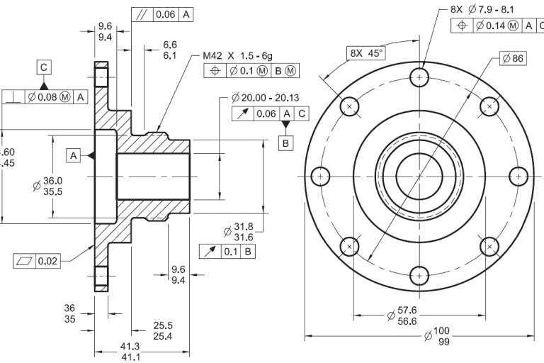
Geometric Dimensioning and Tolerancing (GD&T) is a symbolic language used on engineering drawings to define design purpose and its tolerances.
Instead of conveying the purposes and manufacturing conditions verbally to the manufacturer, GD&T replaces verbal instructions with symbolic language with 1. symbols, 2. Feature control frames, and 3. datums to control the functional geometry of parts on engineering drawings.
To understand GD&T, beginners must learn the key elements used in engineering drawings.
1. GD&T Symbols
GD&T uses standard symbols to control different geometric characteristics of a part.
Each symbol controls a specific geometric property of a feature.
2. Feature Control Frame
The Feature Control Frame (FCF) is a rectangular box used in GD&T to specify tolerance requirements. A typical feature control frame contains of:
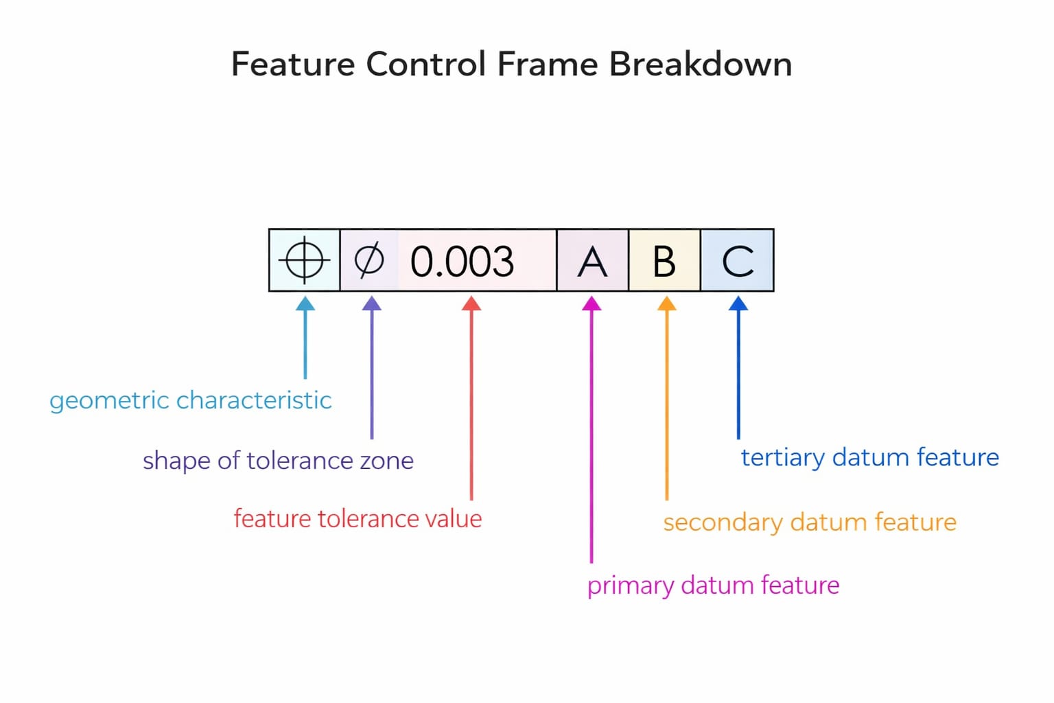
- Geometric characteristic symbol
- Tolerance value
- Datum references
3. Datums
A datum is a reference point, line, or surface used to measure and control other features of a part. Datums help establish a coordinate system that ensures consistent measurement and inspection.
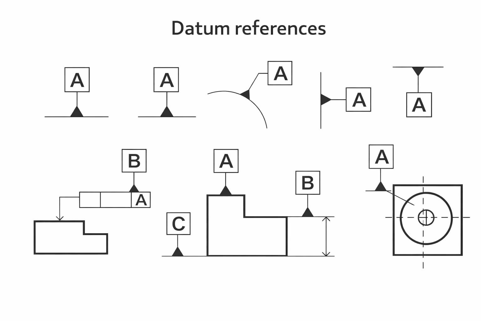
There are three types of datum used:
- Datum A ⟶ Primary reference surface
- Datum B ⟶ Secondary reference surface
- Datum C ⟶ Tertiary reference surface
These references help manufacturers align and inspect parts correctly.
Why GD&T is Important
GD&T helps engineers to:
- Improve product quality
- Ensure proper part assembly
- Reduce manufacturing costs
- Communicate design intent clearly
- Allow controllable variation in manufacturing
Where GD&T is Used in Industry
GD&T is widely used in industries such as:
- Automotive manufacturing
- Aerospace engineering
- Medical device design
- Industrial machinery
- Consumer product design
Companies prefer GD&T to maintain precision, reliability, and consistency in their products.
How to Learn GD&T
- Understand basic engineering drawing concepts
- Learn GD&T symbols and terminology
- Practice reading real engineering drawings
- Use CAD software like AutoCAD, SolidWorks, or Creo
- Work on real design projects
Hands-on practice is the best way to master GD&T concepts.
Advantages of Using GD&T
Using GD&T in engineering drawings provides several advantages:
Better Design Communication
Designers can clearly communicate their design intent to manufacturers.
Higher Product Quality
Precise tolerances ensure parts fit and function correctly.
Reduced Manufacturing Cost
Controlled tolerances allow manufacturers flexibility, reducing production costs.
Global Manufacturing Compatibility
Parts manufactured in different locations will still assemble correctly.
Conclusion
Understanding GD&T basics is essential for job seekers pursuing a career in mechanical design and manufacturing. It helps engineers communicate design requirements clearly and ensures parts function and their purpose.
For beginners, learning GD&T may seem complex at first, but with practice and proper training in institutes like "3D Alchemy", it becomes an invaluable skill in the engineering industry.
Whether you're a student or a professional, mastering GD&T will significantly improve your design accuracy, engineering knowledge, and career opportunities.
Take the next step in your mechanical design career and master GD&T. Join the training program at 3D Alchemy today and see how our practical training can help you become a mechanical design engineer.
Contact us today for free course demo and batch availability.
Ready to Become an Industry Ready Engineer?


Copyright © 3D ALCHEMY | Website by Digieno